Compendium!

In my first post, I mentioned a technical document whose first version was released in late 2021. A few people asked me for additional clarifications about this document and its origins. If you make it to the end of this article, I promise to share the adobo recipe in my next post.
What is it?
It's a document I named «The Amstrad Cpc Crtc Compendium» and which contains the results of an in-depth study of the video components equipping the CPC microcomputers produced by Amstrad in the 1980s.

CRTC is an acronym for "Cathode Ray Tube Controller". The CRTC 6845 is a model of this generic circuit used by many microcomputers designed in the 1980s to facilitate the development of the display electronics of these machines. IBM used it extensively in the IBM PC released in 1981, and it was found in the CGA, EGA, VGA video cards equipping the first PCs and compatibles.
A little over 2 years after its initial publication in December 2021, the Compendium grew from 173 pages in version 1.1 to 284 pages in version 1.7. It has been distributed in English since January 1st, 2022.
It's a free document distributed in PDF format but nevertheless registered under «Creative Commons License».


Why?
I'm very curious and interested in early graphics systems. For several years, I wanted to structure a document describing how the CRTC 6845 works in the CPC context, while incorporating various techniques used in the demoscene world and by myself in some productions.
While developing software on CPC that required technical precision, I realized I was spending a lot of time searching through my notes to find information and sometimes had to redo tests.
I believe a document of this type was necessary to serve as a reliable and proven technical reference for any developer (including myself) while complementing my own knowledge in a living document.
I've also always favored knowledge sharing. The Logon System group has widely demonstrated this philosophy since its creation in 1988.
For whom?
The document is aimed at experienced programmers and/or emulator developers facing the lack of technical documentation from the companies that produced these circuits.
It also contains many less technical chapters to allow everyone to access relevant information that goes beyond the scope of CPC circuits.
As we'll see later, you can't create a document specific to the CRTC on CPC without also describing the machine's architecture and the circuits that work 'together', such as the Z80A (the CPC's processor) or the GATE ARRAY (the circuit that drives all the other circuits in the machine).
When it comes to programming these circuits, you also need to address how this can be done concretely. Implementing sophisticated techniques also requires describing optimization or programming principles on the CPC. These chapters are less complex to understand than managing the internal states of circuits like CRTCs. I think this makes the document quite versatile, with some people being able to benefit only from the optimization methods or fixed-time programming techniques.
The CPCs' CRTCs?
Yes...and no!
Amstrad used 'generic' CRTC 6845 components from 3 manufacturers: Hitachi, UMC and Motorola. It also created its own version of the circuit in an ASIC to minimize its production costs. An ASIC is a specialized circuit that allows different functions to be grouped together on the same circuit. Unfortunately, there was no public documentation for this CRTC « Amstrad »
 Contributeurs aux projets Wikimedia
The document skips CRTC functions not 'exploited' on CPC, such as managing a hardware cursor or text mode, which are used with IBM PCs and their CGA cards. However, it remains usable for users of other platforms who use or are looking for information about this component and who face the same questions and compatibility issues as on CPC.
To that end, I received very positive feedback from users of various machines such as the BBC, IBM PC or even VIDEOTON.
On IBM PC, I had constructive exchanges with people who participated in the AREA5150 demo (Hello Utterchaos & Viler) and are using the document.
 PCem
PCem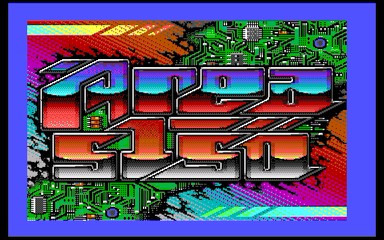
For the curious, Viler published very interesting research on his blog, particularly on the allocation of comparators in an 'asynchronous' architecture:

Finally, as an anecdote, the VIDEOTON is a unique Hungarian machine equipped with a Z80A and having very little video RAM, which makes it an excellent candidate for all video RAM vectorization techniques and especially the line-by-line break technique.
 Contributors to Wikimedia projects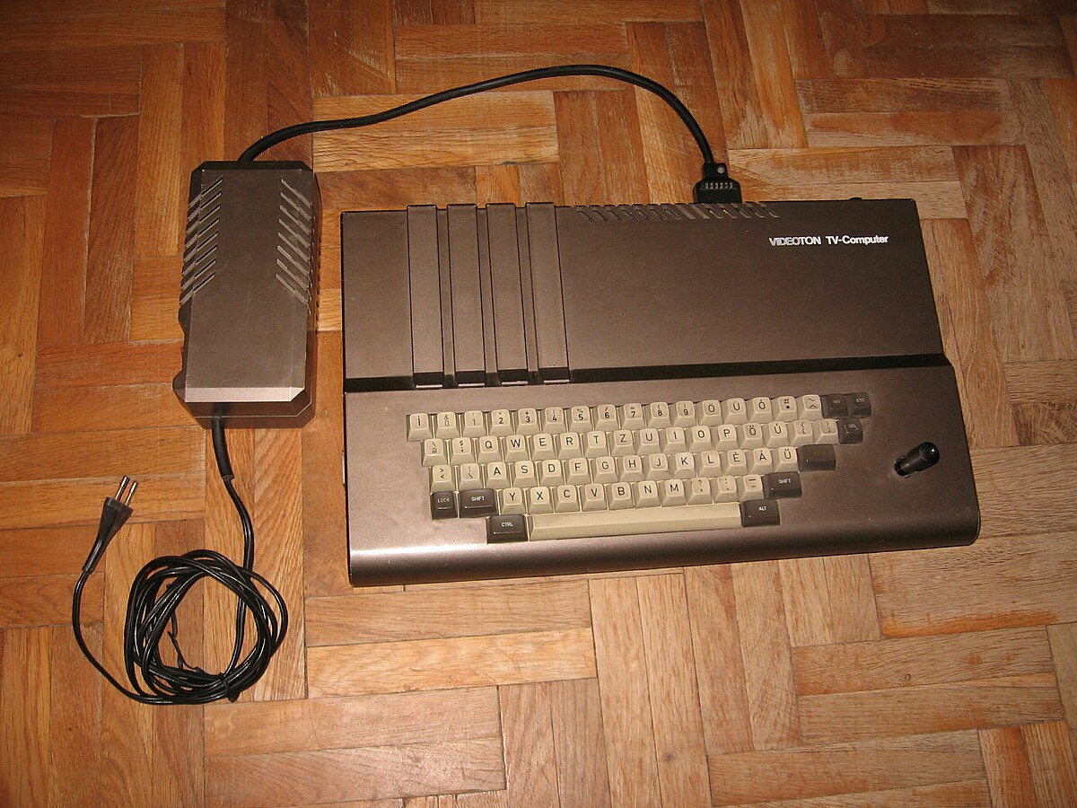
Even though the CRTCs integrated into these different machines are not exactly the same as those present in CPCs, the information in the Compendium proves to be a good basis for investigation and allows me to further corroborate the results stated by my research.
What about official documentation?
The various manufacturers of the circuit, such as Hitachi, UMC, Rockwell, VTI, Motorola and many others, created documents exclusively in English and commonly called «datasheets».
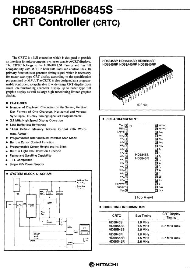
These documents all have roughly the same structure. Some circuits are themselves copies of models from other brands and can't always be distinguished except by the marking on the component. You can find some copy-paste work in these documentations.
The functional specification was quite generic. However, fairly different technical solutions were implemented by engineers to achieve similar 'general' objectives.
However, they didn't go into detail about the solutions they implemented in their documentation, even in the comparative tables of circuits. You can sometimes find vague instructions about value limits without explanation, and there are some errors (for example in the UM6845R document regarding interlace mode, figure 7).
It's therefore impossible with these documentations to truly understand what happened in the circuit, and particularly for all the edge cases of its 3 main functions which are construction, synchronization and display of the image (here understood as 'display authorization').
Consequences...
The differences between these circuits became notable when they were used beyond the recommendations and specifications, particularly by some game programmers and demomakers. Below are some examples:
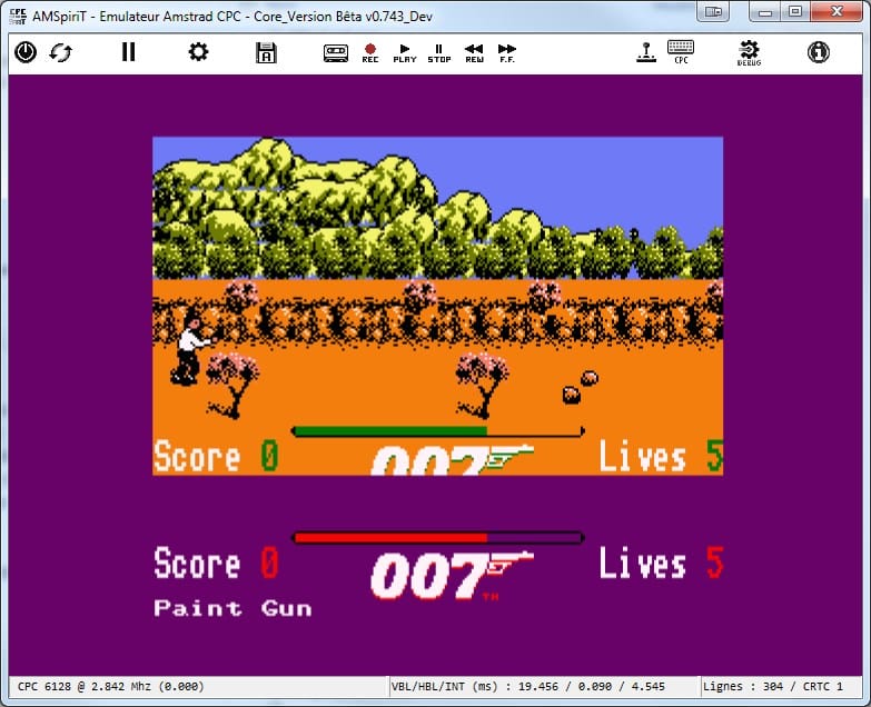
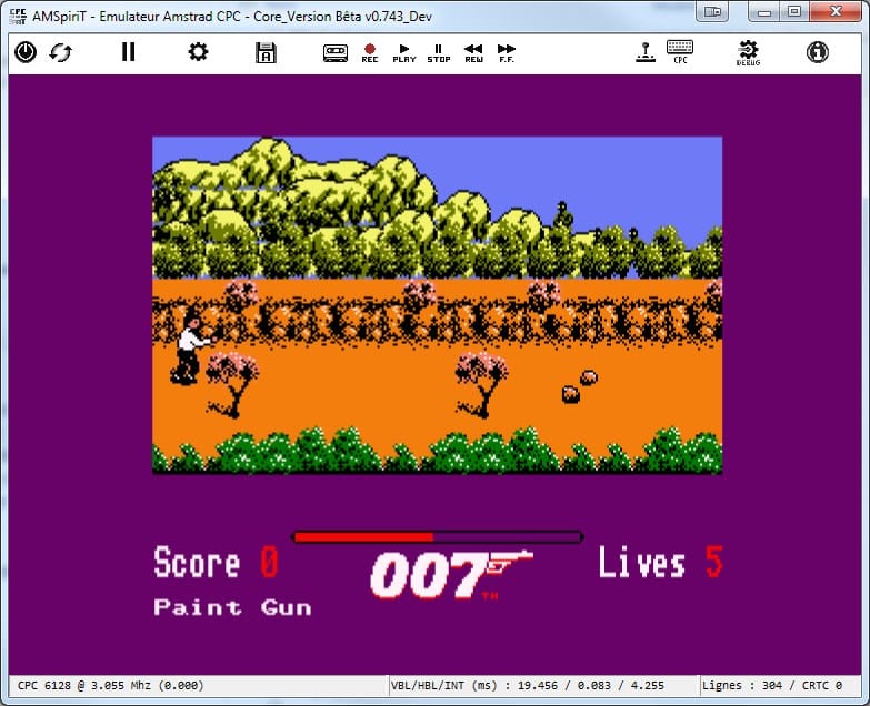
Game '007 The Living DayLights' on CRTC 1 on the left (The HUD is duplicated because of the C4=0 bug) and CRTC 0 on the right (correct display)
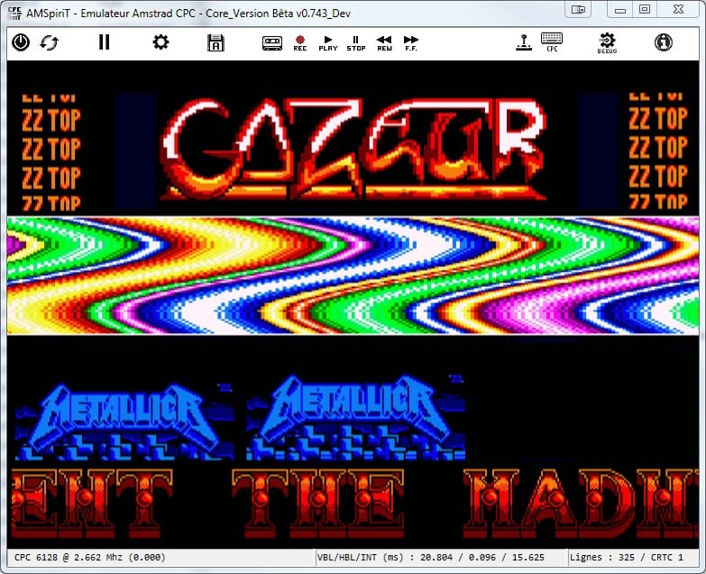
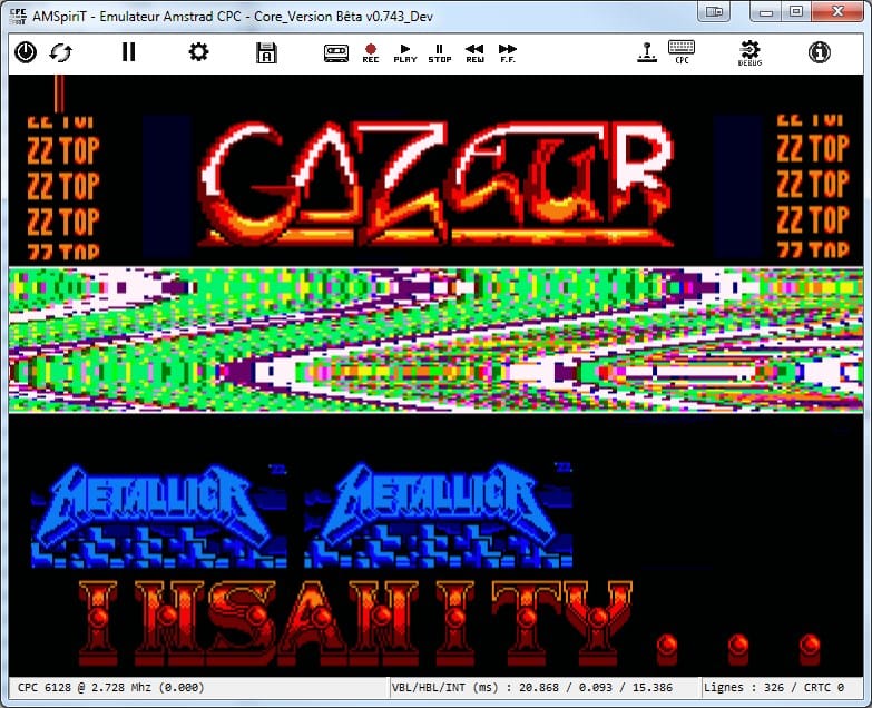
Demo 'Madness' on CRTC 1 on the left and CRTC 0 on the right
Code that works perfectly on one machine may not work at all on another. Generally this results in a loss of sync of the displayed image which manifests as scrolling pixel garbage. The differences can also cause code to lock up.
The question then naturally arose of understanding the origin of these differences in order to remedy them and prevent a program from only being functional for a proportion of the machine's users. Once formally identified, each circuit (or group of circuits) was numbered:
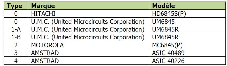
In some extreme cases, compatibility requires small adjustments or rewriting part of the code. In other cases, you may hit dead ends depending on the method used and/or the developer's knowledge of the different circuits. Of course, it's ultimately up to the developer to adapt (or not) their code and/or reduce the nature of the effect presented for the other CRTCs.
In any case, this partly relies on available knowledge and/or research that one has been able to do to understand the intimate workings of the circuits.
Unofficial documentations...
A few demomakers wrote documentations in the 1990s to explain CRTC techniques and which served as a basis and reference for many people afterwards.
Logon System tried to popularize certain techniques, such as the "break", in the monthly "Amstrad Cent pour Cent".
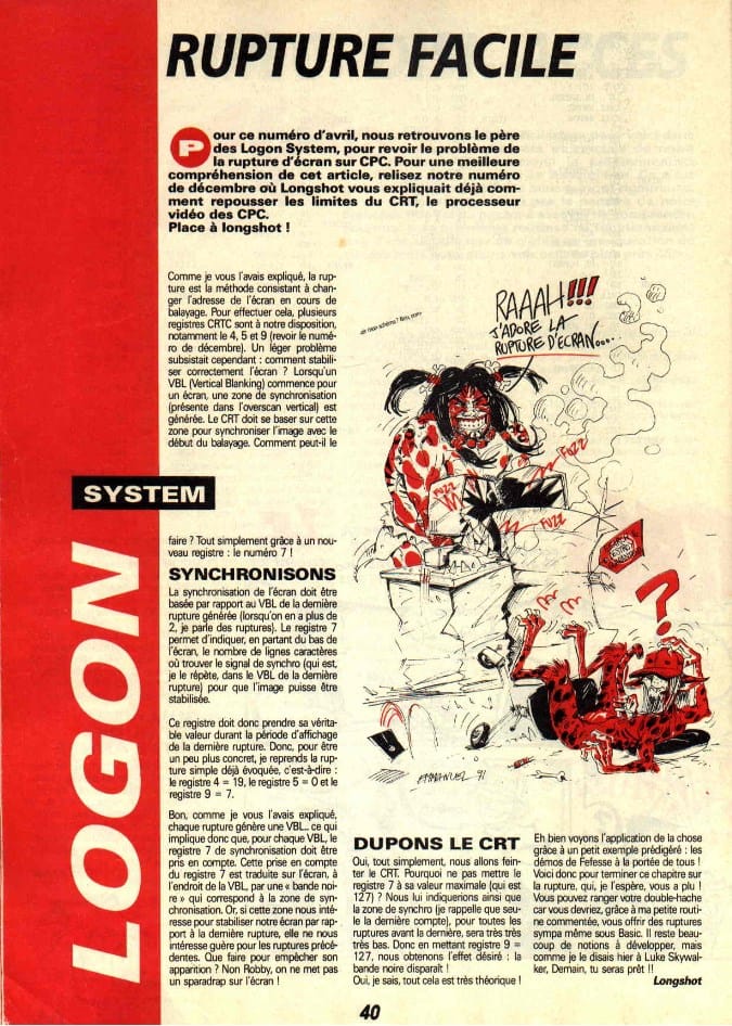
More 'confidential' documentations (which didn't remain so for long) circulated. We can mention Gozeur (greetings Renaud if you're reading this) in the early 1990s and Ramlaid (Greetings Thierry if you're reading this) in 1999.
Even though these documents contained some errors, they had the merit of existing and describing some basic principles of techniques used in demos, such as the "break" and its various declinations, which allow for display vectorization. Unfortunately, these documents were quite poor when it came to explaining why circuits behaved differently depending on their programming. At the time, it was difficult to have all configurations available at will and count the number of different CRTCs actually in circulation.
At best, you could find some warnings indicating that such or such a value was 'radioactive'.
In the years following the 1990s, relatively little progress was made in understanding these circuits. Much of the demoscene that succeeded the disappearance of microcomputing after 1993 primarily lived on the achievements of the previous generation.
However, it should be noted that the portal created by Grim after the 2000s presented several interesting analytical works on the GATE ARRAY, a central circuit of the CPC architecture created by Amstrad and which deals, among other things, with the display of pixels pointed to by the CRTC. The pages on the CRTC remained quite poor, merely displaying in a comparative table the format of registers from technical guides for the 5 identified CRTCs. The portal also contains some notable errors in defining certain registers or functions of CRTC 0 and 1, and wrongly qualifies the 'interlace' modes of these circuits as 'buggy'.
The differences...
A document presenting the real differences between CRTCs remained long an 'Arlesian' in the small world of CPC.
Knowledge of the 'differences' between CRTCs was long summarized in a meager table circulated from fanzine to fanzine, containing superficial, incomplete, sometimes inaccurate or downright fanciful information:
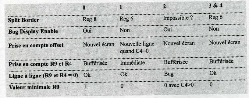
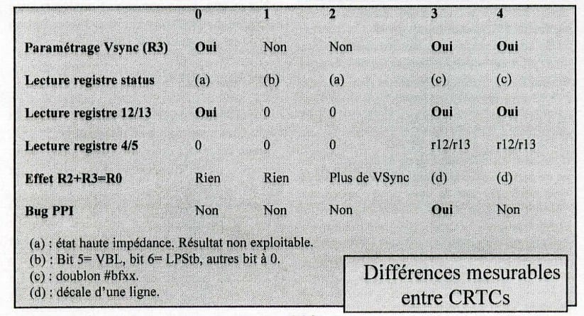
Amslive 19 page 15 (July 2002) / Amslive 18 page 12 (June 2002)
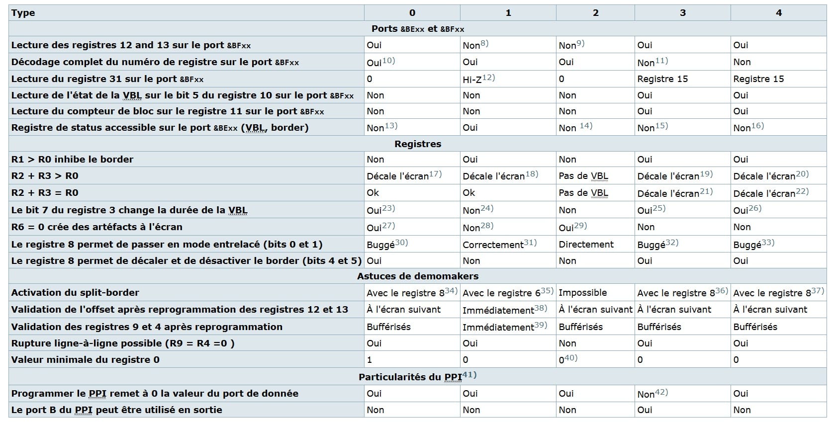
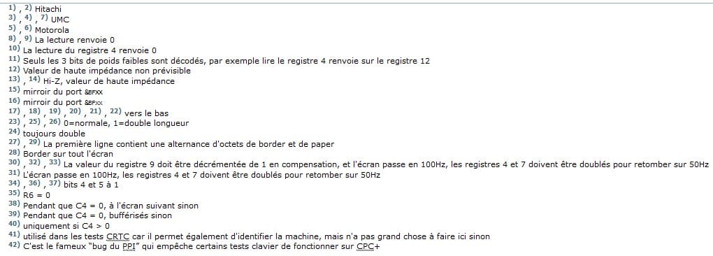
Quasar portal (http://quasar.cpcscene.net/doku.php?id=coding:test_crtc#fn__38)
Like the documentations I mentioned in the previous paragraph, these tables at least had the merit of existing, but they often resembled recipes accompanied by age-old fears based on 'bugs', 'buffering' and forbidden values. For example, never put 0 in R0 on CRTC 0, or else a suck mode triggers! 😏
The study of circuits...
With a trowel?
You can often sum up the operating logic of these circuits by saying they're simple counters that reset to zero when they reach their limit and trigger different states when they reach other values.
This is largely true but things aren't always that simple, otherwise this kind of study would have been done and published long ago.
When it comes to circuits, an electronics method involves 'stripping' the circuit chemically to get a map of its transistors using photos taken via an electron microscope. This has already been done, but the result produced remains indigestible and has led to nothing to date.
The approaches!
To be able to study the logic of these circuits and their differences, you must understand how each circuit manages its counters, its internal states and its 'triggers', trying to guess how and why engineers dealt with such or such a problem.
It's research work that requires making observations, forming hypotheses, establishing experiments to obtain results, then interpreting those results to define conclusions.
I think one of the big problems encountered by the designers of these circuits was the implementation and integration of the so-called 'interlace' functions. These functions promised the customer the ability to improve the readability of the display or double the number of lines (625 lines) at the cost of lowering the frequency to 25Hz of the full display of an image (with the risk of retinal detachment for users in 'video mode' 😅).
Engineers had to find a system compatible with these functions for the technical choices made for managing display construction and synchronization.
A 'software' approach requires long, methodical, sometimes tedious research work, and requires a certain rigor. You must conduct very many tests to validate or disprove all the hypotheses put forward, taking into account the architecture built around the circuit. The result of one test can itself lead to other hypotheses in cascade. This requires new tests, and so on...
Methodology
The first two things I needed to tackle this research were on one hand to eliminate all factors likely to influence the results obtained and on the other hand to generate easily accessible code allowing to study explicit results adapted to the CRTCs tested.
The first problem was solved by defining a fixed reference point independent of circuit parameters, and by adopting a test programming method based on so-called 'fixed-time' programming. This is why these methods and associated tools are documented in the Compendium.
The second problem was to create an experimentation module accessible via a single program and containing tests that could serve as a visual reference and basis for the hypotheses put forward. This was done with the SHAKER program, which contains thousands of tests performed on all CRTCs.
Before solid foundations were established for certain behaviors that had never been studied before, the video method proved very interesting for more easily determining what happened in certain cases. Indeed, as soon as the screen construction is not what the test program expects, the screen loses sync. This demonstrates that the basic hypothesis is incorrect, or that it's correct but one or more other phenomena are involved in the equation. It's sometimes difficult to know what's exactly at the origin of a counting problem and thus of synchronization or display. Frame-by-frame study of video from some tests sometimes made it possible to understand what was happening.
Loss of sync is the most classic phenomenon that every CPC demomaker has repeatedly experienced. To limit the damage, and especially when studying interlace functions, I had to develop different systems to force synchronization.
A classic, which remains quite empirical, is to manage a counter to 'search' for display stability. I had to develop other methods, including one I called 'autosync' which allows automatic synchronization of a break from the second frame.
The objective here is not to list the different test methods, as each subject presents its own challenges and constraints. But the search for these methods is what I think made this work so interesting.
Environment
It was also necessary to take into account the technical environment of the CRTC to study it.
For example, you access circuits via Z80A input/output instructions. The handling of these instructions is not the same depending on the type of circuit, but also depending on the instruction used. So it was necessary to study the electronic logic behind these instructions and describe it as simply as possible, which is far from an easy task.
It's a bit technical, but you must imagine that the Z80A and the CRTC are clocked by the GATE ARRAY, that the Z80A so clocked sends its I/O to the CRTC or to the GATE ARRAY, that the CRTC tells the GATE ARRAY how to manage its interrupts, and that the GATE ARRAY tells the Z80A when it wants to get an interrupt!
I know some who just said "What a mess!"
Moreover, you must not forget that the CRTC doesn't display or synchronize anything at all. It's a 'controller'! It tells the GATE ARRAY at what memory address it should go read the bytes in RAM and convert to pixels, when to stop (or not) displaying pixels (the BORDER on CPC), and when to send horizontal and vertical sync signals to the monitor.
On this last point, many people have written that CRTCs are 'buggy' in 'interlace' mode. This is inaccurate because it's the GATE ARRAY that receives the two types of synchronization signals from the CRTC, but doesn't send them when it receives them. This was probably Amstrad's way of saving the management of 2 sync signals by combining them.
Collaborative work!
For several tests, I was able to call on a few good souls (whom I still thank) to use some of my interactive tests sometimes a bit barbaric to set up, and also present in SHAKER. Indeed, although I have most of the machines, it turned out that GATE ARRAY models presented differences that could be highlighted, and I was far from having all the necessary configurations.
When I hit the limits of software testing, I acquired, thanks to Fred le Fugitif's advice, a digital analyzer which proved useful to 'see' what the signals looked like on certain pins of the circuits studied. This allows me to state that the C-SYNC signal from the GATE ARRAY to the monitor is of XNOR type (bless you). On a machine where the 'fastest' instruction corresponds to 1 µsec, it becomes indeed difficult to detect with a software test phenomena that occur on a scale of 0.0625 µsec.
The emulation in question...
Finally, I quickly sought to work with an emulator author because I thought it was the best way to validate or study certain behaviors of the circuits. My first attempt was unfortunately a failure. Too bad!
I then had the good fortune to discover on a forum the wanderings of David MANUEL (DManu78) who was making his Amspirit emulator while sharing his journey. Despite the enormous and patient work he had already done on the video circuits, he agreed to break down and rethink part of his initial logic to follow that of the Compendium (but the guy didn't give up easily, believe me!).
We were thus able to work together to advance in understanding the mechanisms and bugs present in the different CRTCs and GATE ARRAYs.
If Amspirit contains the Compendium, the reverse is also true.
Amspirit is currently the most reliable and accurate emulator for emulating major CPC components, such as the Z80A, the GATE ARRAY and all versions of CRTCs.
The result of this emulation thus demonstrates the exploitability and reliability of the information present in the Compendium.

Proof of concept!
Proof of concept allows you to validate a principle by demonstrating its feasibility.
Contributeurs aux projets Wikimedia
SHAKER is in itself a realization whose purpose is to demonstrate all the concepts and information described in the Compendium.
You can find there some applications of techniques described in the document, such as that of the 'line-by-line break on CRTC 2' or even 'vertical scrolling at 1/128th of a pixel'.
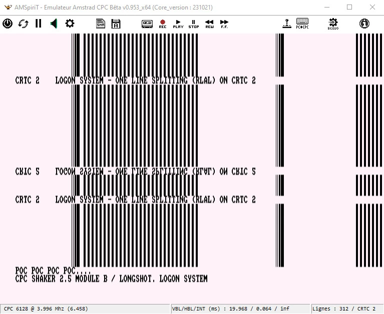
SHAKER 2.5 module B, test 0 : Scrolling Sub Pixel
In some cases, the techniques described were demonstrated in more colorful POCs added to the ADD-ON disk accompanying SHAKER. This was notably the case for the application of RVLL breaks, for work related to HSYNCs which allow for smooth scrolling in pixel modes 1 and 2 on CPC. This is also the case of the small DSC#4 demo which seems to have irritated some people.
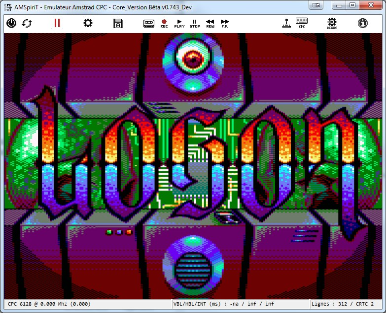
Disque Shaker Addon - Scrolling Horizontal Mode 1 au pixel
Structure of the Compendium!
Official documents
As I mentioned earlier, official manufacturer guides are almost all structured the same way. The general functions of the circuit are briefly described on the first page, with the names of the different pins of the component, their tolerances, periods and brief descriptions.
A few diagrams show the high/low states of different pins over given display periods, but are quite incomprehensible to someone without an electronics background.
A diagram briefly describes the interaction between counters and registers with the location of the internal 'comparators'. A table, which you find on many portals and fanzines, describes the resolution and gives a brief and general description of the role of each register.
Each register is described in order.
It's paradoxical but it's often on the 'interlace' functions that these documents are most verbose. This doesn't make them any less incomplete because it generally boils down to 1 or 2 pages maximum that don't allow you to understand how many problems were handled. In general, in these documents, the descriptions are imprecise, ambiguous, incomplete or even incorrect.
Approach
I had to think about how to present the conclusions of my research.
It was necessary to structure a document presenting a very precise approach to the behavior of each circuit, offering a comparative description in a specific architectural context.
My first approach was to structure a document based on the 3 main functions managed by CRTCs. I remind you here that these are 'construction', 'synchronization' and 'display authorization (border)'.
This approach seemed a priori the most relevant because it allowed grouping counters and registers by function.
For example, the construction of an image groups counter C0 associated with register R0, counter C9 associated with register R9, counter C4 associated with register R4, counter C5 or C9 with register R5, and finally registers R12/R13 with an internal variable (VMA).
But the detailed description of these different counters and registers quickly posed readability problems, and especially when it turned out that registers were in 'an awkward position'. To a lesser extent, this is for example the case with R1, which participates in BORDER management, but which is also involved more or less closely in managing video address processing. Or again when specific processing mechanisms for certain functions differ depending on synchronization logic. And things didn't improve at all with the 'interlace' functions.
Another solution was to take up the logic of manufacturer guides and detail the registers in their numerical order since all designers had approached the issue that way. This approach also showed its limitations in the perspective of addressing the logic of comparators established by designers. In a functional 'Russian doll' logic, image construction functions are hierarchized. 'Words' make up a line (R0), lines that make up a 'character' (R9), and 'characters' make up a frame (R4). As long as you don't step outside the 'standard' display logic, describing them in this order presents no problem. Things get much more complicated if you enter the logic of chaining these counters and can group the concepts of line and frame in a single 'CRTC word'.
For example, if you want to describe what happens with R0=0 having set R4=0, R9=0, it's better to have explained what R4 and R9 correspond to before addressing R0, and even more so if you give concrete and schematic examples of video techniques like breaks.
This led me to reorganize the document until adopting the approach that seemed best to me, and incidentally have it validated by one of my friends who is a scientific researcher.
Solution
The solution that seemed most viable to me was to describe the registers individually, grouping them by function, and ordered in the most logical order to avoid addressing subjects requiring too many references to concepts not yet addressed.
The functions grouping these registers are themselves ordered with the same concern. We 'construct' (1) a screen, which we can then 'synchronize' (2) and on which we account for display areas (3) and 'video pointer management' (4).
The integration of practical cases, combined with numerous diagrams, I believe facilitated understanding of the most complex chapters.
This is an approach that can perplex people who don't read the most complex chapters of the document in order to first grasp all the concepts and definitions. Someone too confident in their knowledge who went straight to a technical chapter without going through the definitions of concepts and states might flounder despite the presence of many diagrams.
The document was submitted to several reviewers who did not give me critical feedback.
The document adopts the following general structure:
- General information / Terminology / Acronyms (chapters 1, 2, 3)
- The CRTC on the CPC, its access, and other CPC circuits (chapters 4, 5)
- Principles
- Les principes de construction, synchro, affichage d'une image (chapitre 6)
- Les principes de synchronisation de l'étude (chapitre 7)
- Les principes de conversion de la mémoire en pixel en interaction avec la Z80A (chapitre 8)
- Pixel display and graphics mode management by the GATE ARRAY (chapter 9)
- Counting function (construction):
- Registre R9 (généralités, délais, règles par CRTC) (chapitre 10)
- Registre R5 (généralités, ajustement & intéractions, RFD) (chapitre 11)
- Registre R4 (généralités, RLAL crtc 0 & 2) (chapitre 12)
- Registre R0 (généralités, règles par CRTC, RVLL, RVI, mises à jour, cas particuliers) (chapitre 13)
- Synchronization function:
- Registre R3 (généralités, vsync, hsync, mises à jour, interruptions) (chapitre 14)
- Registre R2 (généralités, hsync, vsync, affichages)(chapitre 15)
- Registre R7 (généralités, csync et vsync, conditions, mécanismes de protection et de retard) (chapitre 16)
- Display function:
- Registre R1 (généralités, règles, gestion vma/vma') (chapitre 17)
- Registre R6 (généralités, règles et conflits par crtc) (chapitre 18)
- Registre R8 (généralités, fonctions skewdisp, interlace (modes, programmation, parité, ligne additionnelle, mid vsync, comptages par crtc) (chapitre 19)
- Video pointer: Registers R12/R13 (general information, calculation, updates by crtc, delays) (chapter 20)
- Read registers. General information, status (chapter 21)
- Fullscreen & centering (chapter 22)
- Development:
- Trucs et astuces (mise à jour R12/R13, usage commun registres, attente vsync, valeur 0, ....) (chapitre 23)
- Temps fixe (introduction, méthodes, interruptions, outils, méthode, ...) (chapitre 24)
- Durée des instructions en Z80A sur CPC (chapitre 25)
- Interrupts (general information, r52 counter, triggering, modes, crtc and interrupts) (chapter 26)
- CRTC identification (chapter 27)
I think I've completed this little overview of the design of this document.
I am grateful to the people who provided me with information and gave me constructive feedback, whether on small spelling or technical mistakes, in order to improve the document. As I indicate in the preamble, "truth takes up little space, but error occupies an infinite number of places".
In the meantime, I invite you to reload the French version of version 1.7, which had a table of contents problem. I have also just corrected an error that was pointed out to me in chapter 4.4.4.
https://shaker.logonsystem.eu/ACCC1.8-FR.pdf
Longshot / Logon System